| Picture | Description | |||||||||||||||||||||||||||||||||||||||||||||||||||||||||||||||||||||||||||||||||||||||||||
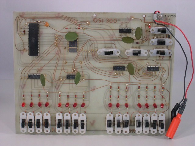 OSI300 6502 CPU
(Image courtesy of EarlyComputers.com) |
Model 300 Trainer ~1976 OSI 300 Manual (courtesy of Bill Dromgoole) |
|||||||||||||||||||||||||||||||||||||||||||||||||||||||||||||||||||||||||||||||||||||||||||
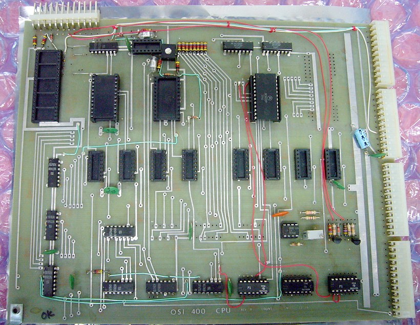 OSI400 6502 or 6800 CPU
(Image courtesy sdf.org) |
Model 400 CPU Supports one of 6502, 6502A, 6501, 6512, Motorola 6800, 6800A, 6802, 6802B PROM supports up to two of the following: OSI 65A Serial Monitor, OSI 65V Video Monitor, OSI 65F Floppy disk bootstrap RAM: optional 1Kx8 of 2102 Serial: ACIA based 20ma current loop or RS-232, up to 100,000 baud. Parallel: Supports one of the following PIA devices for up to 16 I/O lines: 6820, 6520, 6522, 6530, 6830 Buffering for up to 250 OSI boards. Provisions for user supplied front panel and DMA capability Addressing for 2 PROMS: $FExx, $FFxx RAM: $0000- $03FF PIA: $FDxx ACIA $FCxx OSI400 schematics |
|||||||||||||||||||||||||||||||||||||||||||||||||||||||||||||||||||||||||||||||||||||||||||
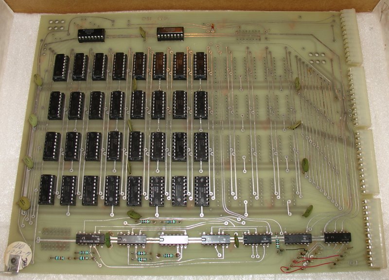 OSI420 4K Static RAM
 |
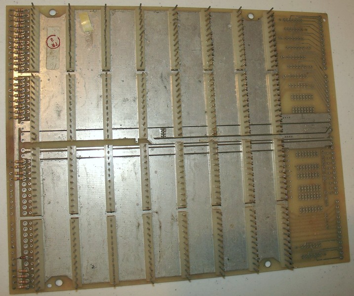
Model 420 4Kx8/4Kx12 static RAM memory
board Uses 2102 1Kx1 static memories, with optional battery backup using 2 on-board NiCd cells or external battery. It has 18 address bits allowing for 256K of memory in a system. It can be populated as 4Kx12 for use with the 560Z PDP-8. Address: any 4K memory address $0000-$0FFF OSI420C schematics |
|||||||||||||||||||||||||||||||||||||||||||||||||||||||||||||||||||||||||||||||||||||||||||
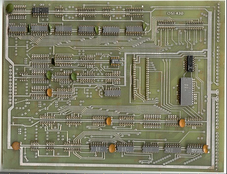 OSI430 Cassette & Analog I/O
 OSI430B Cassette & Analog I/O
(Image courtesy of Bill Dromgoole) |
Model 430 / Model 430B © 1977 Cassette & Analog I/O
OSI430B manual (courtesy of Bill Dromgoole) |
|||||||||||||||||||||||||||||||||||||||||||||||||||||||||||||||||||||||||||||||||||||||||||
 OSI440 Video board
(Image Courtesy Bill Dromgoole) |
Model 440B Video board OSI440B schematics
|
|||||||||||||||||||||||||||||||||||||||||||||||||||||||||||||||||||||||||||||||||||||||||||
 OSI450B & 455 Eprom Boards
(Image courtesy sdf.org) |
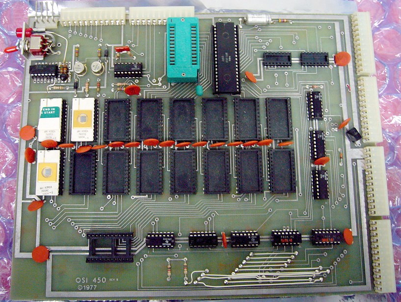
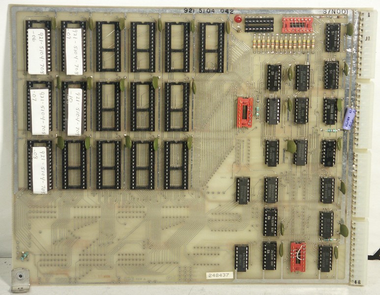
Model 450B 8K Eprom & Parallel I/O
+ prom programmer Model 455 4K Eprom & Parallel I/O © 1977 These boards provide EPROM storage and up to 16 lines of parallel I/O. (req +5, -9v) Full address decoding anywhere in 64K address space. 4K or 8K Uses 6820 PIA at $xFxx 455 Board: up to 16 1702 type PROMS (4K max) 450 board : up to 16 6823 type PROMS (8K max), includes onboard EPROM programmer (req -50v programming voltage) |
|||||||||||||||||||||||||||||||||||||||||||||||||||||||||||||||||||||||||||||||||||||||||||
 OSI460Z 3 CPU Expander
(Image Courtesy Bill Dromgoole) |
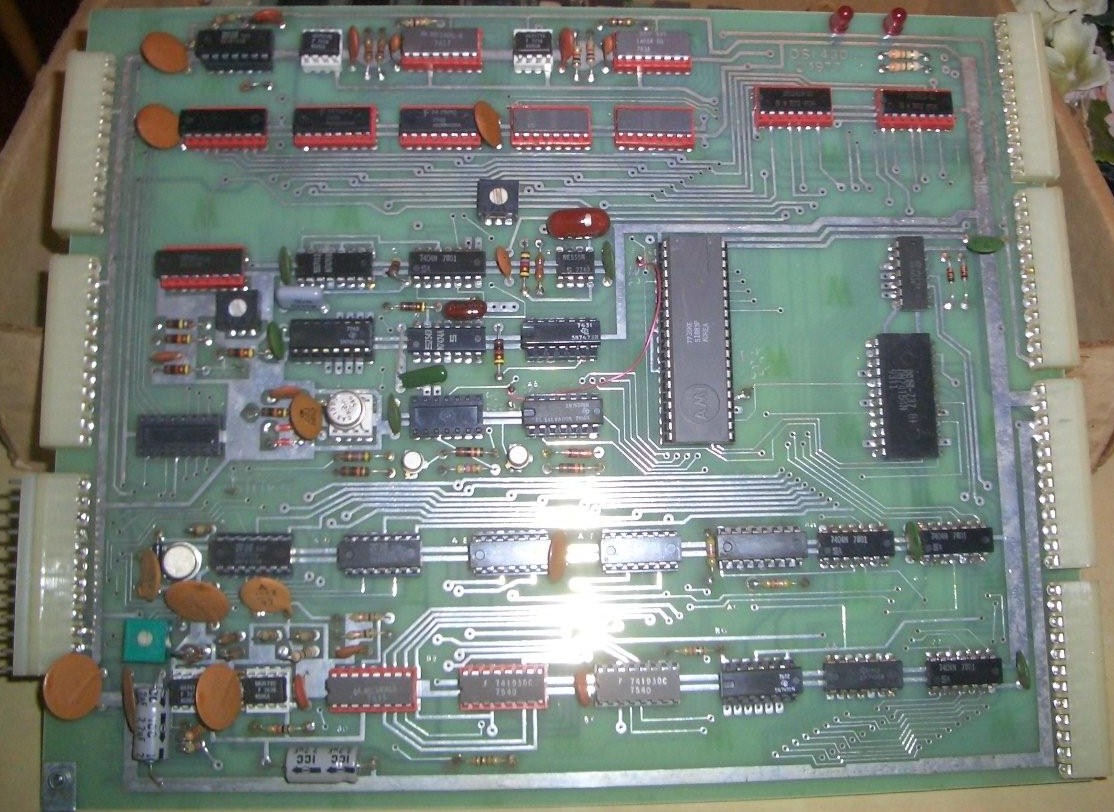
Model 460Z CPU Expander
The 460Z 3 CPU Expander board comes ready to accommodate a Z-80 and 6100 CPU as well as one of a Signetics 2650, Fairchild F8, or RCA COSMAC 1802. In additon to the 3 processors it accommodates 4 PIAs for control plus several multiplexers and demultiplexers. The 3 CPU expander runs downstream of the 6502 host. The 6502 executive has full line-by-line control of the 460Z and can reach the bus through a 4K mapped "porthole". It can run the 460Z CPUs at full speed or in a step at a time, monitor at full speed, "trap" certain instructions, start and stop the host processor, permit "general" memory access and in every way permit full multiprocessor operation. |
|||||||||||||||||||||||||||||||||||||||||||||||||||||||||||||||||||||||||||||||||||||||||||
 OSI470 Floppy Disk Controller
|
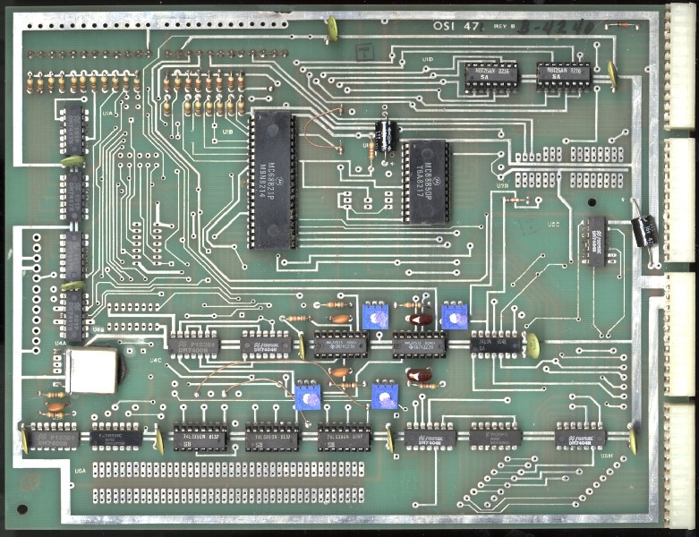
Model 470 disk controller board(same as Model 471)
ACIA: DCD wired to -(-Index & -Sector) OSI470 floppy schematics
OSI470 printer I/O schematics |
|||||||||||||||||||||||||||||||||||||||||||||||||||||||||||||||||||||||||||||||||||||||||||
 OSI480 Backplane
(Image courtesy of Bill Dromgoole) |
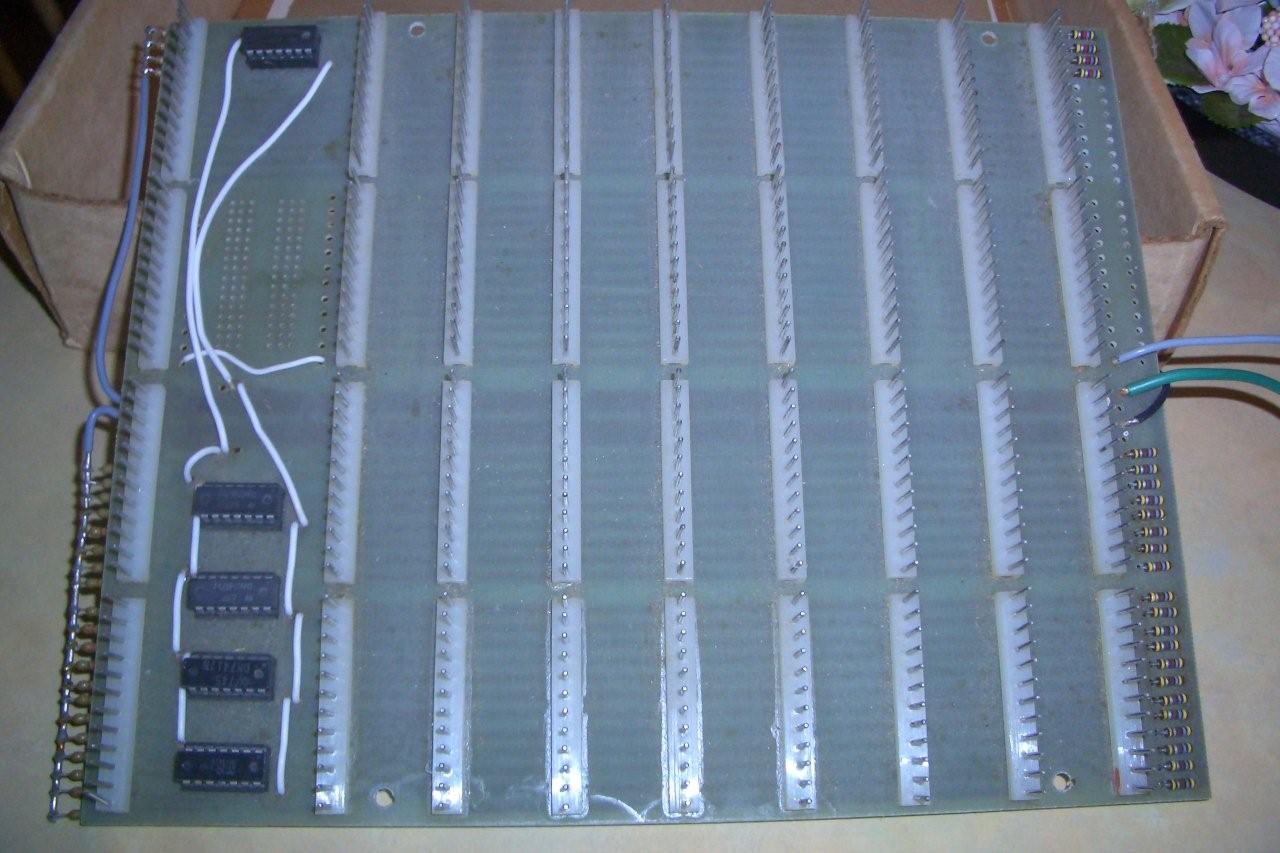
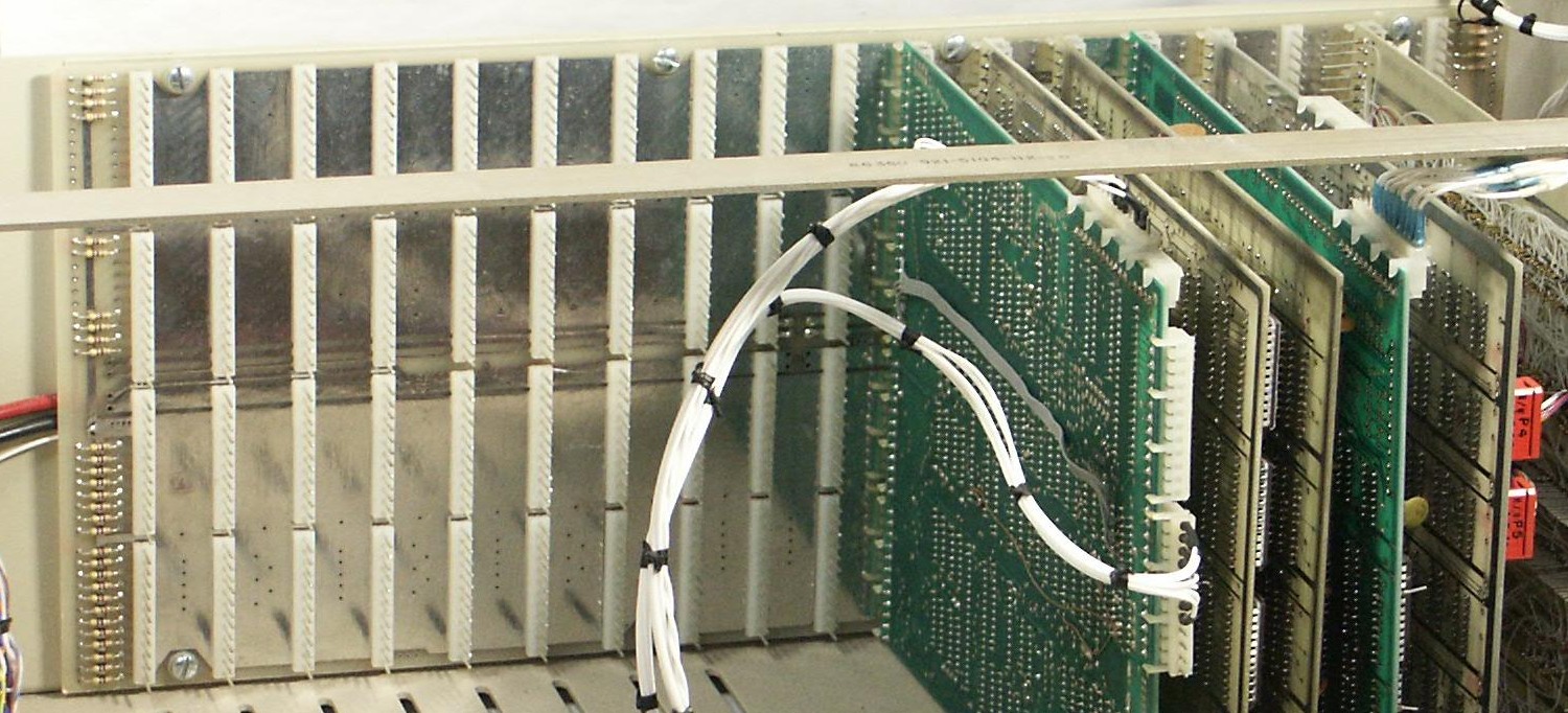
Model 480 Backplane
8-slots with buffering allowing additional 480 boards to be connected together for up to 250 slots OSI480 manual (courtesy of Bill Dromgoole) |
|||||||||||||||||||||||||||||||||||||||||||||||||||||||||||||||||||||||||||||||||||||||||||
 OSI495 Prototyping
|
Model 495 Prototyping board Supports up to 40 16-pin package chips & 8 40 pin chips |
|||||||||||||||||||||||||||||||||||||||||||||||||||||||||||||||||||||||||||||||||||||||||||
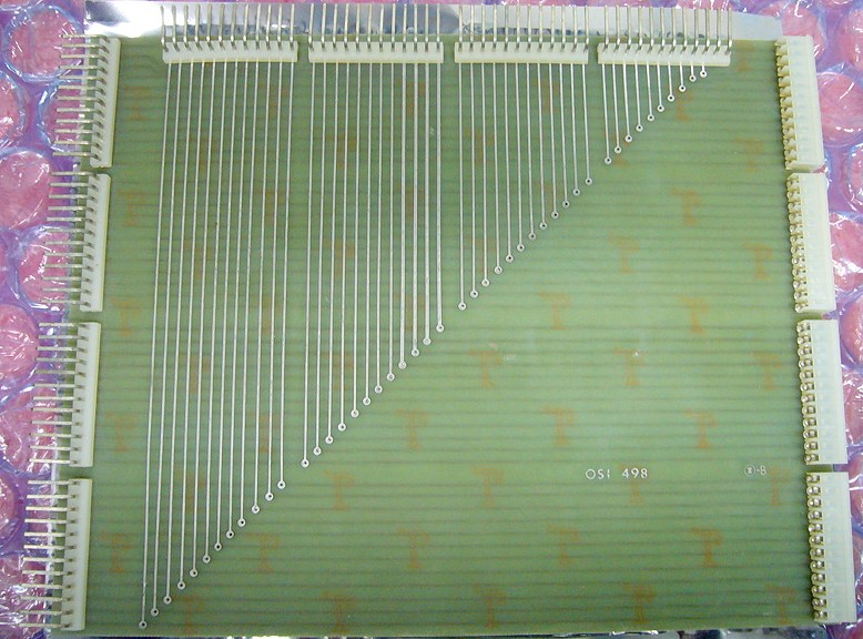 OSI498 Card Extender
(Image courtesy sdf.org) |
Model 498 Card Extender Used to extend a card out of the cage for easy servicing. Has connectors on the top to service Challenger system boards, and along the edge for some OSI 400 configurations. |
|||||||||||||||||||||||||||||||||||||||||||||||||||||||||||||||||||||||||||||||||||||||||||
(Image courtesy of Bill Degnan)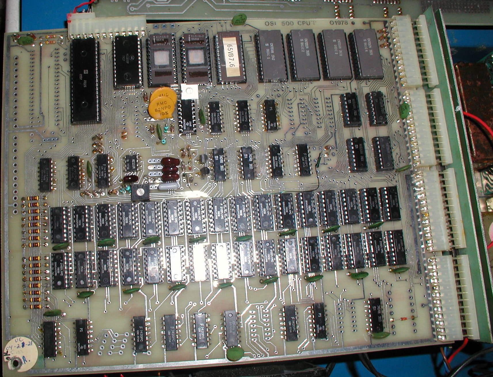 OSI500 CPU RAM ROM IO
  OSI500B CPU RAM ROM IO
|
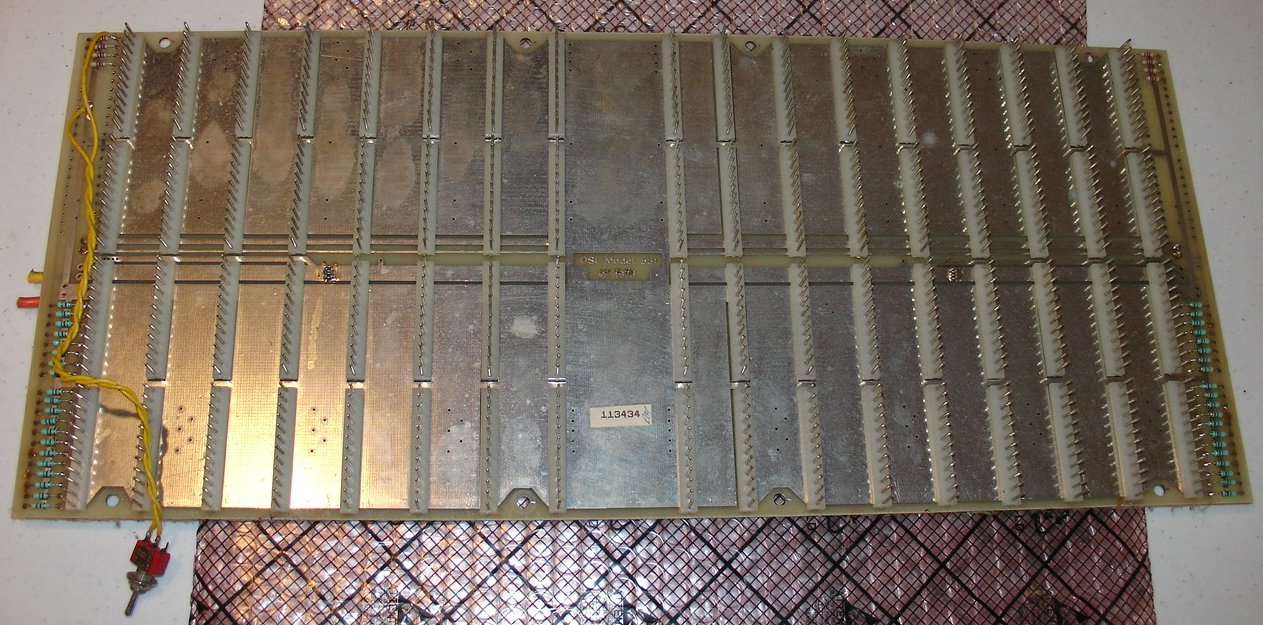
Model 500 CPU © 1977, update
© 1978, and the revised Model 500B CPU © 1978 6502 CPU board with 4 2Kx8 ROMs supplied with Microsoft Basic in ROM, 4K of on-board RAM, RS-232 or current loop, ACIA, PIA, 3 256x8 system ROM pages. Can be used as the controller for 560Z. Can be used with 430B audio cassette interface, 440B video graphics board, & floppy disk system. (There are at least two versions of the original 500 board, plus a 500B board that has a single EPROM socket, replacing the three 256byte 1702 EPROMS.)
Works with OSI 65A serial PROM monitor, 65V video PROM monitor, and floppy disk bootstrap PROMs Used in OSI C2P systems with OSI540A monochrome graphics adapter. |
|||||||||||||||||||||||||||||||||||||||||||||||||||||||||||||||||||||||||||||||||||||||||||
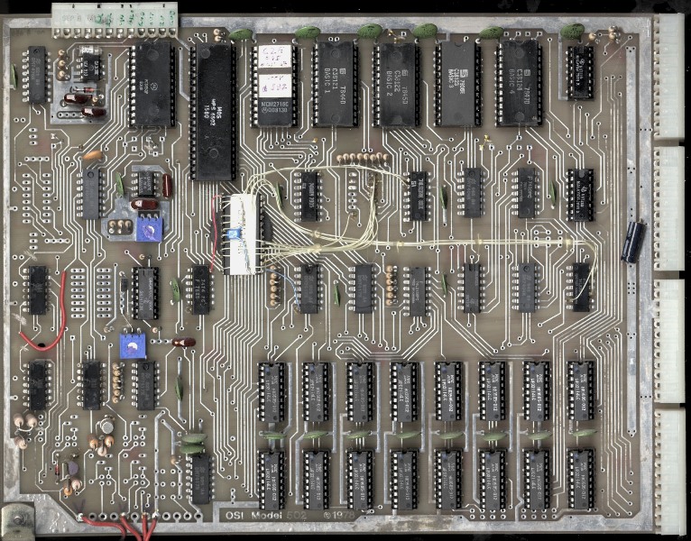 OSI502 CPU Board
|
Model 502 CPU board © 1978 CPU board w/ ROM, ACIA 8K Basic in ROM via 4 2Kx8 ROMS, 2K Monitor ROM, 8K RAM
|
|||||||||||||||||||||||||||||||||||||||||||||||||||||||||||||||||||||||||||||||||||||||||||
 OSI505 CPU + Disk Ctrl
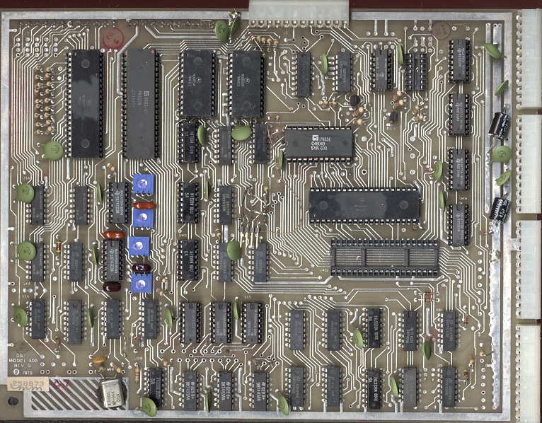 OSI505B CPU + Disk + I/O
|
Model 505 & Model 505B CPU &
Floppy Interface Board © 1979 CPU board w/ ROM, ACIA, Floppy Disk I/O, Real Time Clock
505B has I/O at $C704-C70E for connection to A15 I/O board which contains connectors for keypads, joystick, buffered I/O contains A0-A3, �2, R/W, D0-D7 for Head End Cards. (MDS-since it requires external hardware, without hardware installed, looks like NULLREAD space I think...) Uses disk I/O connector board A-13 Case uses port I/O connector board A-15 505B Used in OSI C4PMF systems OSI505A schematics (courtesy of Bill Dromgoole) |
|||||||||||||||||||||||||||||||||||||||||||||||||||||||||||||||||||||||||||||||||||||||||||
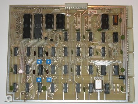
 OSI510C 3 CPU Board
|
Model 510 Triple CPU Board (6502, Z80, 6800) © 1979 OSI510C schematics (courtesy of Bill Dromgoole) |
|||||||||||||||||||||||||||||||||||||||||||||||||||||||||||||||||||||||||||||||||||||||||||
 OSI512 unknown
|
OSI 512 clock generator?
Unknown board. It seems to be some kind of FSK encoder that takes a clocked data stream and turns it into bursts of 4.7 MHz (mark) or 6.5 MHz (space). Perhaps this is part of the RF home control system? OSI512 schematics (courtesy of Bill Dromgoole) |
|||||||||||||||||||||||||||||||||||||||||||||||||||||||||||||||||||||||||||||||||||||||||||
 OSI520B
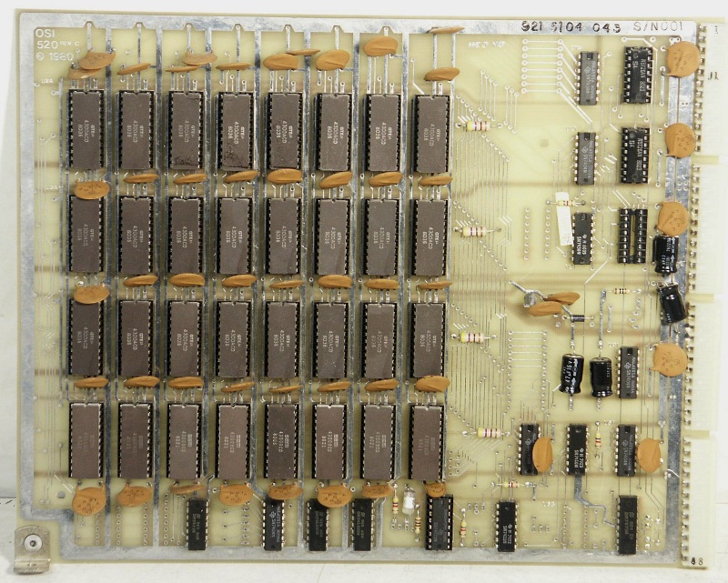 OSI520C 16K RAM Board
|
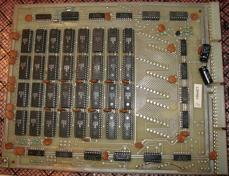
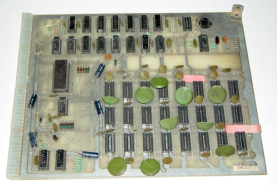
Model 520 RevB 16K RAM board © 1977 Uses 32 4Kx1 EMM 4200 /GTE 4300 22-pin static RAMs (3 voltages, +5, +12, -9) fully populated to 16K RAM OSI520C schematics (courtesy of Bill Dromgoole) |
|||||||||||||||||||||||||||||||||||||||||||||||||||||||||||||||||||||||||||||||||||||||||||
 OSI522 48K RAM Board
|
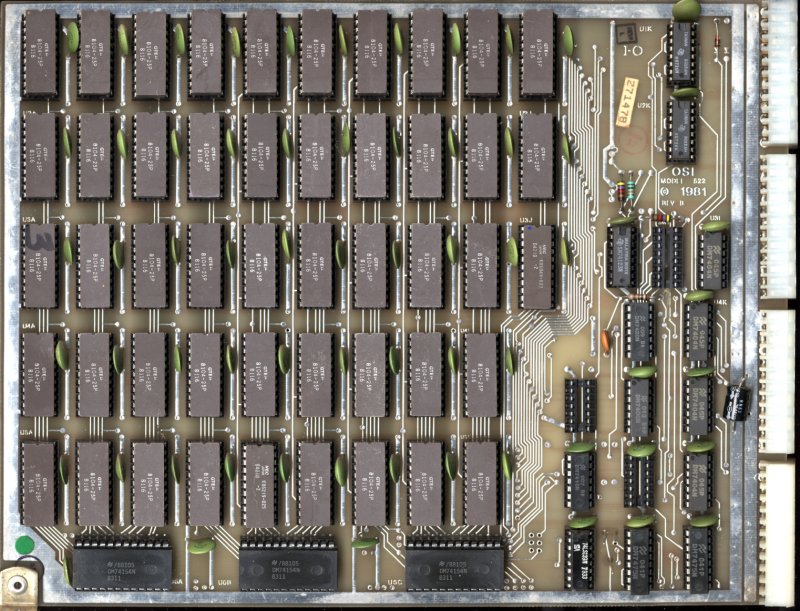
Model 522 48K RAM board © 1981 Uses 48 1Kx8 22 pin DIP RAM chips (GTE 8104/ NEC D421D) fully populated to 48K RAM OSI522 schematics (courtesy of Bill Dromgoole) |
|||||||||||||||||||||||||||||||||||||||||||||||||||||||||||||||||||||||||||||||||||||||||||
 OSI524 64K RAM Board
|
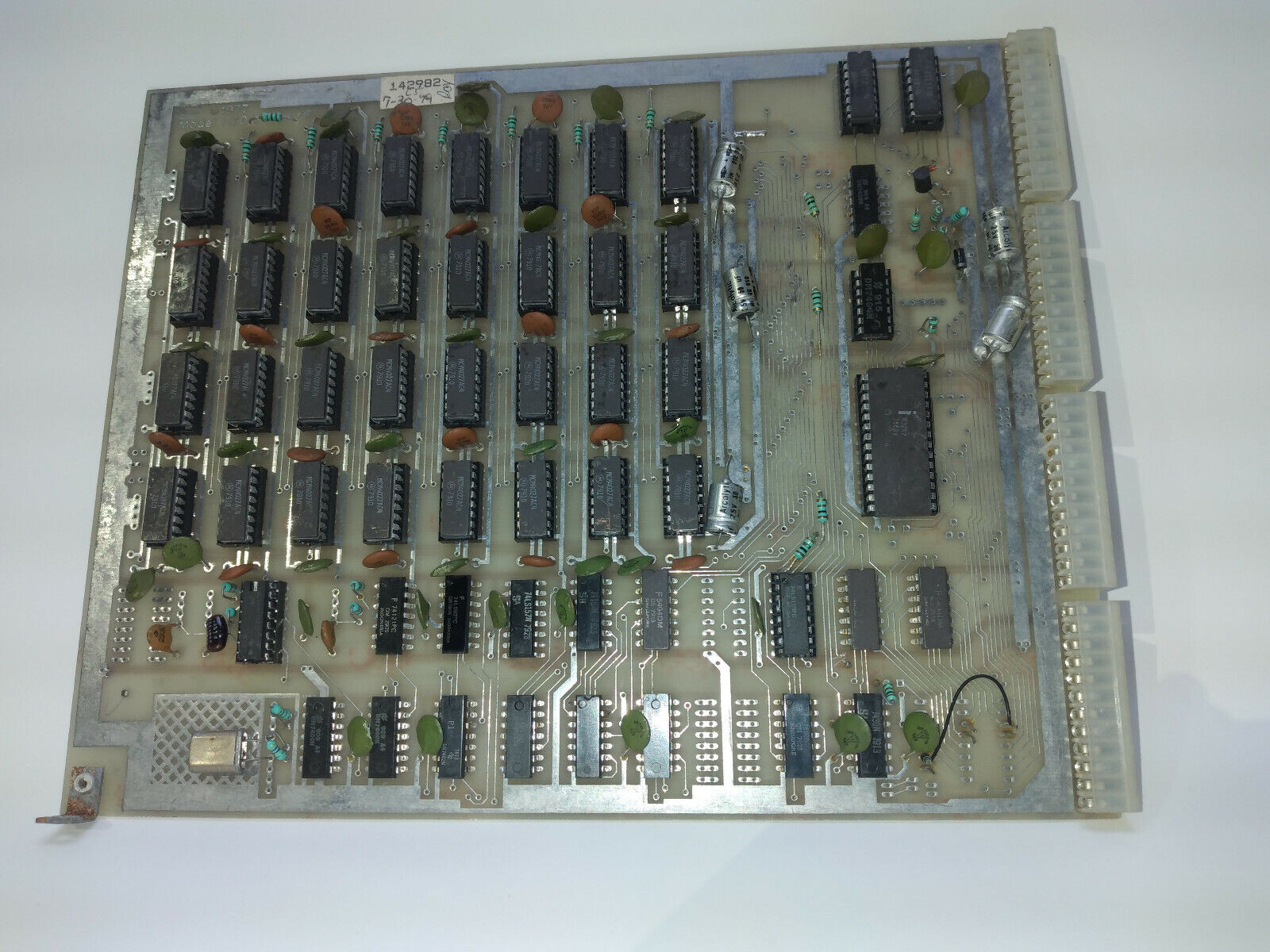
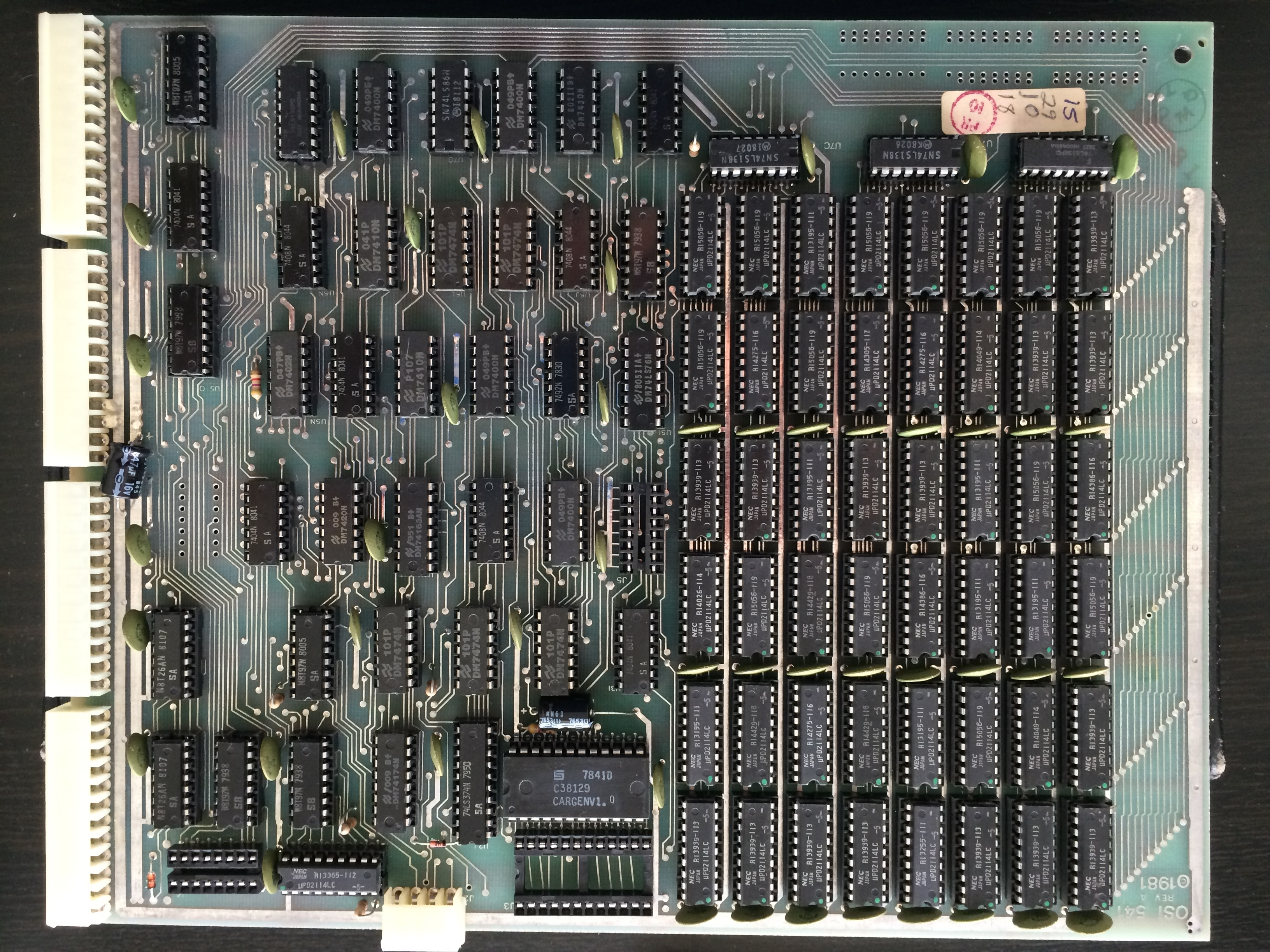
Model 524 64K Static RAM board ©
1981 Uses up to 32 2Kx8 static RAM (NEC D4016D-1) but generally populated with 24 chips yielding 48K |
|||||||||||||||||||||||||||||||||||||||||||||||||||||||||||||||||||||||||||||||||||||||||||
 OSI525 16K Dual Port RAM
|
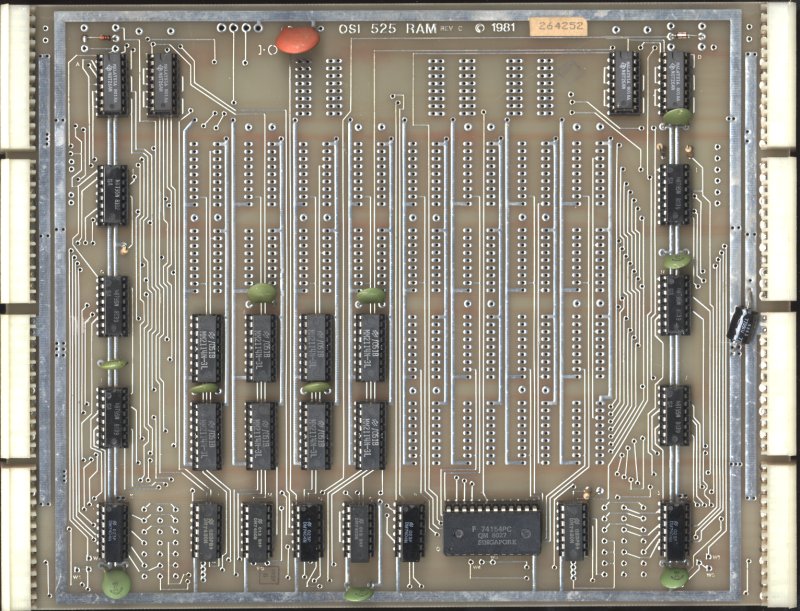
Model 525 16K Dual Port RAM ©
1981 Uses 4K, 8K, or 16K of 2114 1Kx4 static rams, configurable as single or dual port. Used in Hard Disk systems OSI525 schematics (courtesy of Jonathan) |
|||||||||||||||||||||||||||||||||||||||||||||||||||||||||||||||||||||||||||||||||||||||||||
 OSI527 24K Static RAM Board
|
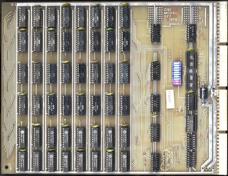
Model 527 24K static RAM board ©
1978 Usually populated as 8K, 16K, 24K board using 2114 static rams. Additional address decoding for up to 1MB (A6-A19). Used in OSI C4PMF |
|||||||||||||||||||||||||||||||||||||||||||||||||||||||||||||||||||||||||||||||||||||||||||
 OSI530 DRAM Board
(Image courtesy of Roy W) |
Model 530 Dynamic RAM Board Can be populated for 16K using 4027 4kx1 16pin DRAM chips. Requires +5/+12/-9 Has address decoding for up to 20 bits and can only be run at up to 1 MHz system clock. OSI530 schematics and Intel DRAM ctrlr (courtesy of Bill Dromgoole) |
|||||||||||||||||||||||||||||||||||||||||||||||||||||||||||||||||||||||||||||||||||||||||||
 OSI535 DRAM Board
|
Model 535 4116 Dynamic RAM Board Uses up to 24 4116 dynamic RAM chips for 48K of memory. Requires +5/+12/-5(-9v) OSI535 schematics and Intel DRAM ctrlr (courtesy of Bill Dromgoole) |
|||||||||||||||||||||||||||||||||||||||||||||||||||||||||||||||||||||||||||||||||||||||||||
 OSI538 Universal Memory Board
|
Model 538 Universal Memory board
© 1980 Contains 16 28pin dip sockets. May be populated with +5v only EPROM, ROM or static RAMs. Supports up to at least 8K EPROM. |
|||||||||||||||||||||||||||||||||||||||||||||||||||||||||||||||||||||||||||||||||||||||||||
 OSI540A Video Board (Image courtesy of Bill
Degnan)
OSI540A Video Board (Image courtesy of Bill
Degnan)
|
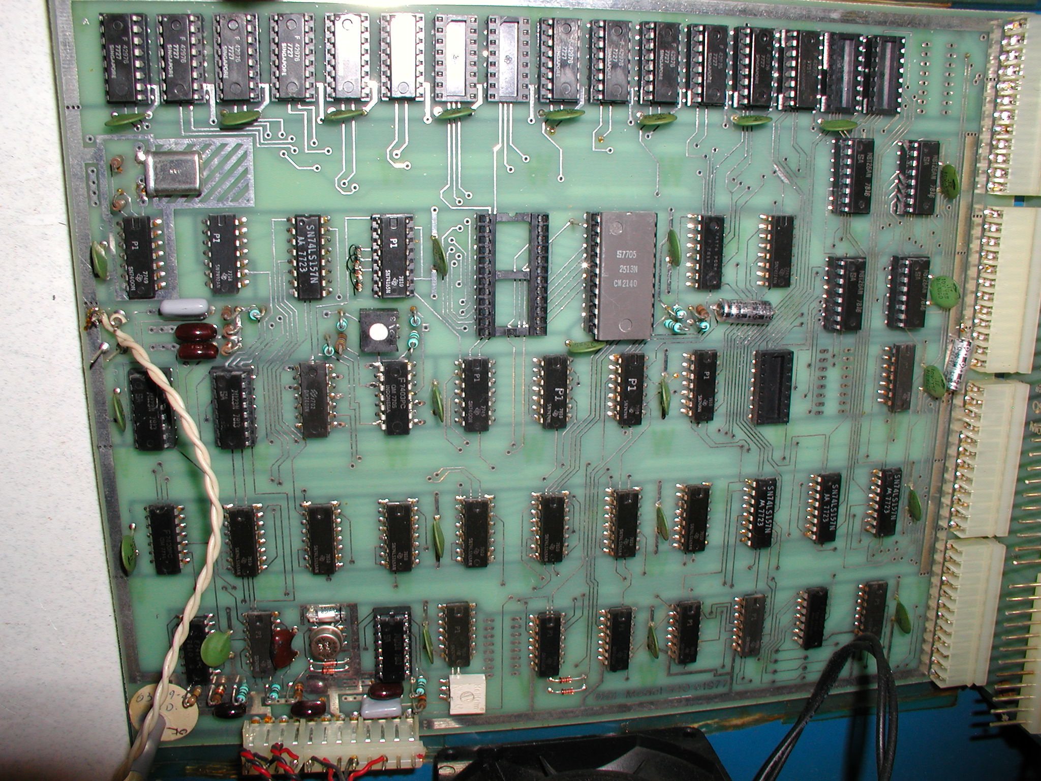
Model 540 Rev A video board © 1977 |
|||||||||||||||||||||||||||||||||||||||||||||||||||||||||||||||||||||||||||||||||||||||||||
 OSI540B Video Board
|
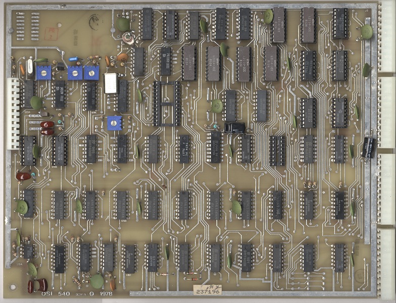
Model 540B video board © 1978 |
|||||||||||||||||||||||||||||||||||||||||||||||||||||||||||||||||||||||||||||||||||||||||||
 OSI541 OSI 541 Hi Res Graphics Expander (courtesy of Jeff Ferguson)
|
Model 541 Hi Resolution Graphics Expander© 1981 (Ma/Com) OSI541 schematics Layout info (courtesy of Jeff Ferguson) |
|||||||||||||||||||||||||||||||||||||||||||||||||||||||||||||||||||||||||||||||||||||||||||
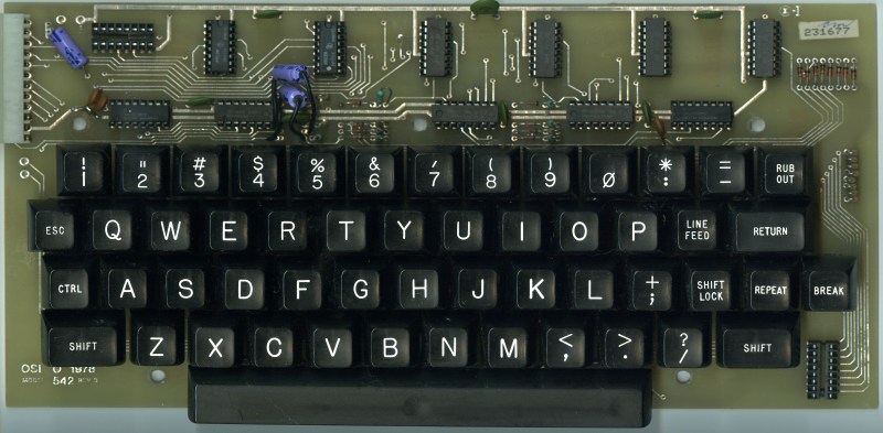 OSI542B
Polled Keyboard + Sound 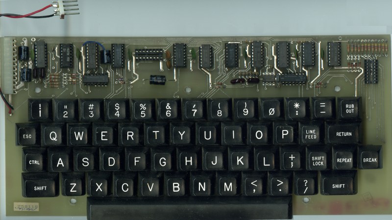 OSI542C Adds reset delay
|
Model 542 ©1977, Model 542B ©1978, and Model 542C ©1980 Polled
Keyboards
Tone enable when bit 1 (0x02) is set at $DE00 Tone generator: frequency out = 49152/I where I = value stored at $DF01(~192Hz - 49152hz) DAC: Capacitively coupled output from an R2R resistor DAC of value stored @ $DF01 OSI542B schematics OSI542C schematics (courtesy of Bill Dromgoole) |
|||||||||||||||||||||||||||||||||||||||||||||||||||||||||||||||||||||||||||||||||||||||||||
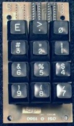 OSI543 Numeric Keypad
|
Model 543 Numeric Keypad © 1980 Numeric Keypad accessory. Used with OSI542 polled keyboard |
|||||||||||||||||||||||||||||||||||||||||||||||||||||||||||||||||||||||||||||||||||||||||||
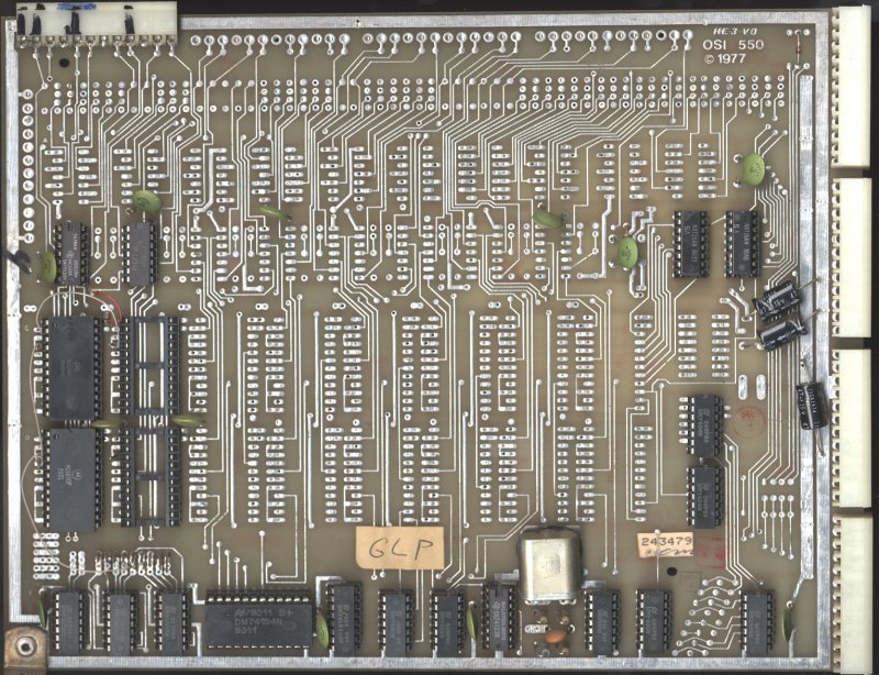 OSI550 Serial I/O Board
|
Model 550 16 port 6850 Serial Port
Board © 1977 (CA-10x) Populated with up to 16 6850 ACIA. Typically used with multishare system and serial system (C3-series) although it can be used with any backplane based system. Mapped $CF00-$CF1F (ACIA 0 to ACIA 15) each port uses 2 addresses OSI550 schematics (courtesy of Jonathan) |
|||||||||||||||||||||||||||||||||||||||||||||||||||||||||||||||||||||||||||||||||||||||||||
 OSI555 Multi I/O Board
|
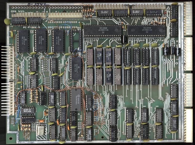
Model 555 Multi I/O expansion & RAM © 1979 4K RAM $D000
|
|||||||||||||||||||||||||||||||||||||||||||||||||||||||||||||||||||||||||||||||||||||||||||
 OSI560Z CPU Board
(Image courtesy of Bill Dromgoole) |
Model 560Z CPU expander © 1977 OSI560Z manual (courtesy of Bill Dromgoole) |
|||||||||||||||||||||||||||||||||||||||||||||||||||||||||||||||||||||||||||||||||||||||||||
|
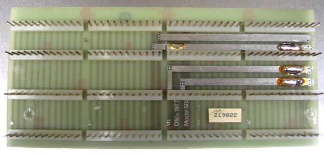
OSI565 board
|
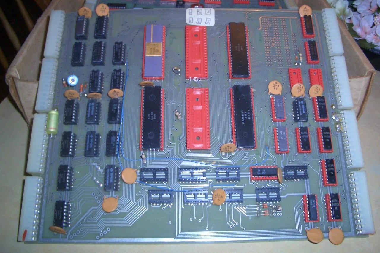
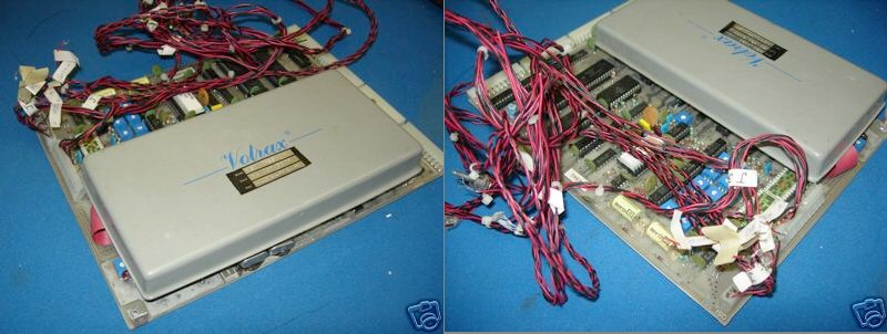
Model 565/CA-14 Votrax interface board & votrax module The CA-14 voice I/O module is composed of the OSI 565 PC board and the Votrax VSK Voice output module. The Votrax voice synthesizer module has the capability of generating English speech phonetically. The supporting software simply feeds the phoenetic spelling of English words to the module which generates medium quality spoken words. Generates all English phonemes and 4 levels of inflection. CA14 also includes voice recognition experimenters area with a five filter feature extractor with zero crossing detectors and envelope filters. CA-14 in conjunction with CA-22 high speed analog I/O module provides a complete voice recognition lab. |
|||||||||||||||||||||||||||||||||||||||||||||||||||||||||||||||||||||||||||||||||||||||||||
 OSI567
 |
Model 567/CA-15 Universal Telephone Interface (UTI) The Universal Telephone Interface provides the host computer with general purpose telephone communications capability. Includes 300 baud internal modem. Generates and decodes Touch-Tone signals. Includes multiplexers to route spoken voice out to external devices like recorders, voice recognition circuts, A/D converters and can accept spoken words from several sources to the telephone. It interface to the phoneline with a FCC aproved CBT DAA data coupler. When including the Votrax voice module it is referenced as CA-15V OSI 567 UTI-Votrax Manual March 1980.pdf (courtesy of lowrybt1 ) |
|||||||||||||||||||||||||||||||||||||||||||||||||||||||||||||||||||||||||||||||||||||||||||
 OSI570 CA-12 controller board
|
Model 570 controller board for
CA-12 © 1980 Contains interface circuit for the 572 3 parallel I/O board, part of the CA-12 package. |
|||||||||||||||||||||||||||||||||||||||||||||||||||||||||||||||||||||||||||||||||||||||||||
 OSI570B I/O & Clock Board
|
Model 570B Multiple Accessory Bus w/ 8
Port I/O & Real Time Clock (CA-20) © 1980 Contains National Semiconductor NS58167 real time clock chip, 6821 PIA, and battery holders for 3 AA size batteries. 8 16-pin DIP sockets for external interfacing Head End Cards. Needs 1 OSI slot in backplane. Recommended for C2 & C3 series computers, may also be made to work in C4P & C8P. |
|||||||||||||||||||||||||||||||||||||||||||||||||||||||||||||||||||||||||||||||||||||||||||
 OSI572 PIA Remote Board
|
Model 572 3 PIA expansion (CA-21) 1978 3 PIA (6821) expansion board with OSI 48-bus connectors can be used as head end card or on OSI 48 backplane. Also comes configured with prototyping area. Included as part of CA-12 96 line parallel I/O which used 2 OSI572 boards with OSI570 controller board |
|||||||||||||||||||||||||||||||||||||||||||||||||||||||||||||||||||||||||||||||||||||||||||
 OSI573 EPROM programmer
|
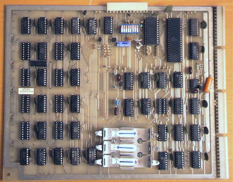
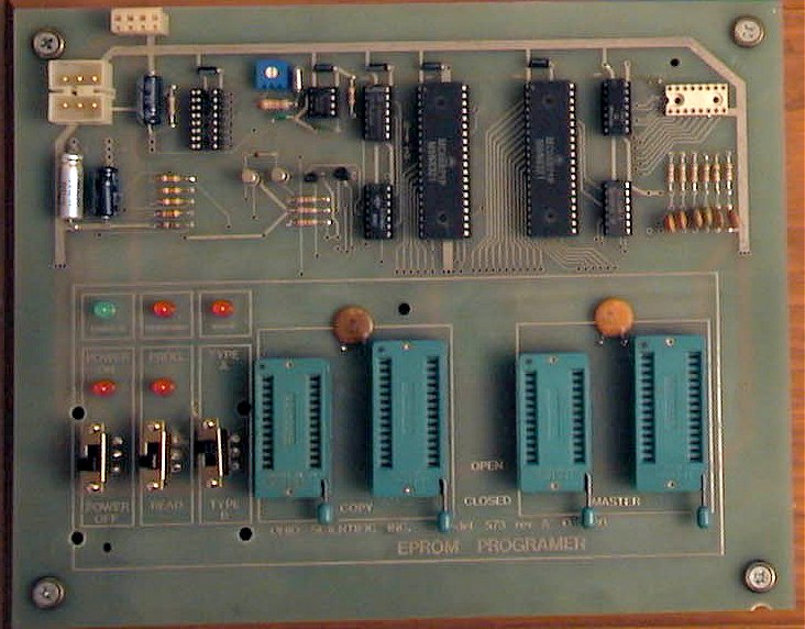
Model 573 EPROM programmer (CA-23) Head End Card EPROM Programmer for 1K to 8K EPROMS. |
|||||||||||||||||||||||||||||||||||||||||||||||||||||||||||||||||||||||||||||||||||||||||||
 OSI574 Analog I/O
(Image courtesy of No Logic) |
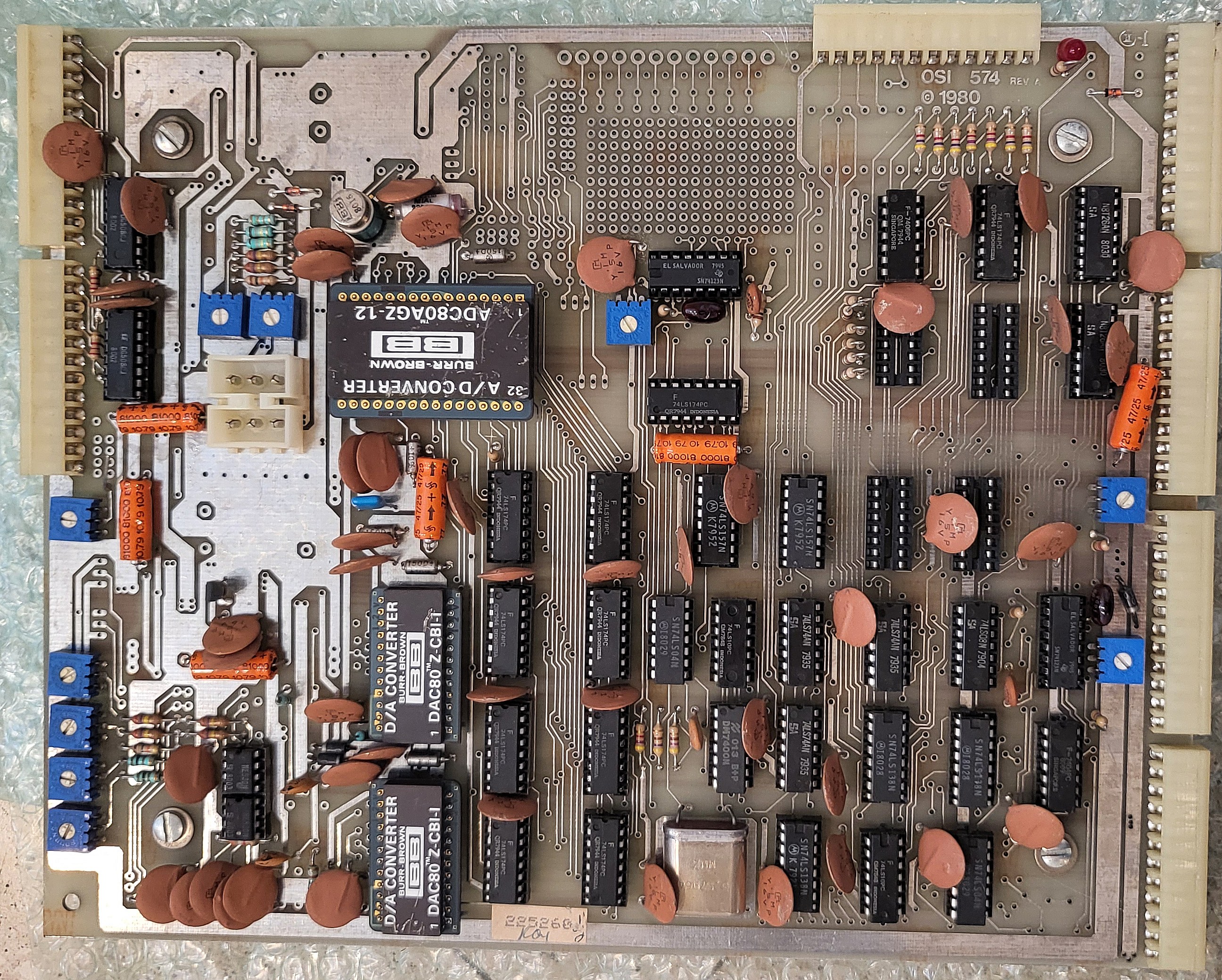
Model 574 Analog I/O Board (CA-22)
© 1980 Head End Card Analog I/O Board - Analog I/O Designed as a high speed analog I/O but differs from other head end cards in that it can be plugged directly into the computers standard bus. 16 channel analog multiplexor, sample & hold. 8 or 12 bit operation. 66K samples/sec 8bit 28K in 12bit. 2 high speed DAC, 8 or 12 bits. 3 TTL level inputs, 6 open collector outputs. Contains 2 Burr-Brown "ADC80AGZ-12" and 2 Burr-Brown "DAC80 Z-CBI-I" Factory configured for +/-10v. OSI574 schematics OSI574 manual ADC80, DAC80, SHC298AM chips |
|||||||||||||||||||||||||||||||||||||||||||||||||||||||||||||||||||||||||||||||||||||||||||
 OSI575 Prototyping Board
|
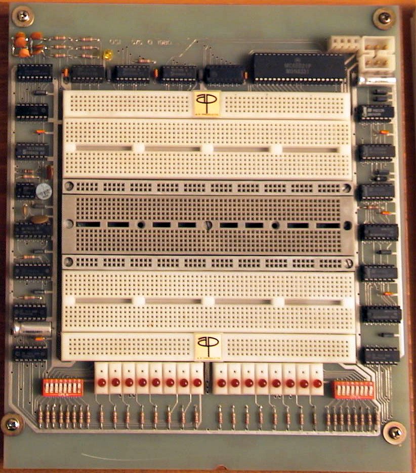
Model 575 Prototyping board (CA-24) Head End Card Prototyping board. Solderless breadboard design. Contains clock Generator 25K-70KHz, and 16 stage divider. Features PIA as well as provisons for direct user connection of devices such as 6850 ACIA. Also features 16 switches and 16 LEDs. |
|||||||||||||||||||||||||||||||||||||||||||||||||||||||||||||||||||||||||||||||||||||||||||
 OSI580 Board
|
Model 580 8 slot backplane Backplane contains 8 rows for use in C8P style cases. |
|||||||||||||||||||||||||||||||||||||||||||||||||||||||||||||||||||||||||||||||||||||||||||
 OSI581 Board
|
Model 581 17 slot backplane Backplane contains 17 rows for use in C3 style long cases. |
|||||||||||||||||||||||||||||||||||||||||||||||||||||||||||||||||||||||||||||||||||||||||||
 OSI582 Board
(Image courtesy Sarkis Daniel) |
Model 582 4 slot backplane Backplane contains 4 rows for use in C4P style cases. |
|||||||||||||||||||||||||||||||||||||||||||||||||||||||||||||||||||||||||||||||||||||||||||
 OSI583 Board
|
Model 583 18 slot backplane Backplane contains 18 rows for use in C3 style long cases. |
|||||||||||||||||||||||||||||||||||||||||||||||||||||||||||||||||||||||||||||||||||||||||||
 OSI590 Hard disk ctrl
|
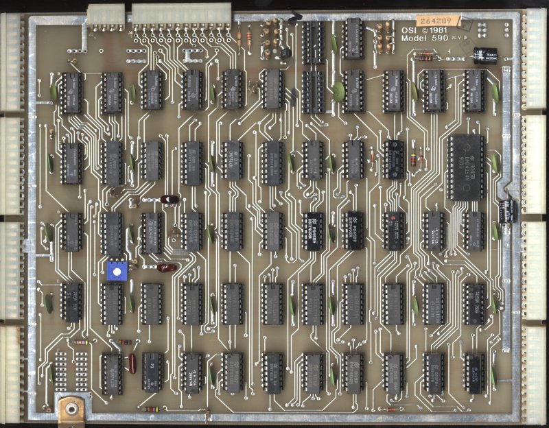
Model 590 Hard Disk Interface &
memory controller © 1981 Base of hard disk interface. Contains 12 pin board connector for OSI disk interface cards (592, 594, or 596) and 2 16-pin headers for cables. Contains 2nd OSI 48 bus for connection to OSI 525 dual port static RAM board. Configurations to support a variety of Winchester, Shugart, and Okidata drives. CD-74 74MB, CD-36 36MB, CD-28 28MB, CD-23 23MB, or CD-7 7MB hard drives. |
|||||||||||||||||||||||||||||||||||||||||||||||||||||||||||||||||||||||||||||||||||||||||||
 OSI592 Hard disk interface
(Image courtesy of Ron Bihler) |
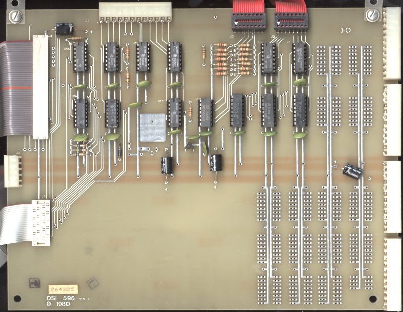
Model 592 Okidata Hard Disk Interface
© 1977 Used with CD-74 74MB Winchester disk drive OSI592 schematics (courtesy of Bill Dromgoole) |
|||||||||||||||||||||||||||||||||||||||||||||||||||||||||||||||||||||||||||||||||||||||||||
|
OSI594 Hard disk interface
|
Model 594 Shugart Hard Disk Interface
© 1980 Used with CD-28 29MB Winchester disk drive |
|||||||||||||||||||||||||||||||||||||||||||||||||||||||||||||||||||||||||||||||||||||||||||
 OSI596 Hard disk interface
|
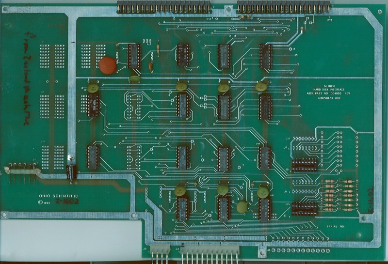
Model 596 Hard Disk Interface ©
1980 Contains 50 pin cable to Shugart SA 1004 Hard Disk 20 pin cable to attach to Hard Disk controller (SA1000?) 12 pin plug bridges to 590 Also has 2 16 pin cable to attach to OSI 590 board Disk controller interface the (SA1000?) attaches to top of this board OSI596B schematics (courtesy of Bill Dromgoole) |
|||||||||||||||||||||||||||||||||||||||||||||||||||||||||||||||||||||||||||||||||||||||||||
 OSI598
Hard disk ctrl
OSI598
Hard disk ctrl
| Model 598 Hard disk controller for
Shugart SA1004 © 1982 Contains interface to directly connect to Shugart SA1004 8" hard disk 4K of 2114 RAM One 50 pin cable header and one 20 pin cable header connect to SA1004. Replaces OSI 590, OSI 525, OSI 596 |
|||||||||||||||||||||||||||||||||||||||||||||||||||||||||||||||||||||||||||||||||||||||||||
 OSI600
Super Board
OSI600
Super Board
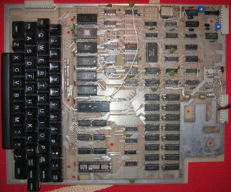
| Model 600 SuperBoard II © 1978
&
Model 600D Superboard II © 1980 Complete computer on one circuit board. Contains 6502 CPU, RAM, ROM, BASIC in ROM, Keyboard, Cassette & video out Video arranged in 32x32 display, 24x24 visible. Keyboard $DFxx (uses inverted values compared to 540 polled KB interface, bit is 0 when key pressed) Superboard II Supports 64x16 display (48x12 visible), Sound Output (DAC) with Color video expansion option and Populated RS-232 |
|||||||||||||||||||||||||||||||||||||||||||||||||||||||||||||||||||||||||||||||||||||||||||
 OSI610 Expansion Board
|
Model 610 disk expansion for 600 board
© 1978 Contains disk controller & decoder logic similar to 470 board along with up to 24K static RAM. Used for expansion and real time clock functionality The 600 board + 610 board are used togeher with a floppy drive to make a C1PMF |
|||||||||||||||||||||||||||||||||||||||||||||||||||||||||||||||||||||||||||||||||||||||||||
 OSI620 Bus Expander
|
Model 620 Superboard bus expander Contains 40 pin socket for connection to OSI 600/610 board and buffers to interface to OSI48 backplane board (OSI480, OSI582) for additional expansion. |
|||||||||||||||||||||||||||||||||||||||||||||||||||||||||||||||||||||||||||||||||||||||||||
 OSI630 color video
|
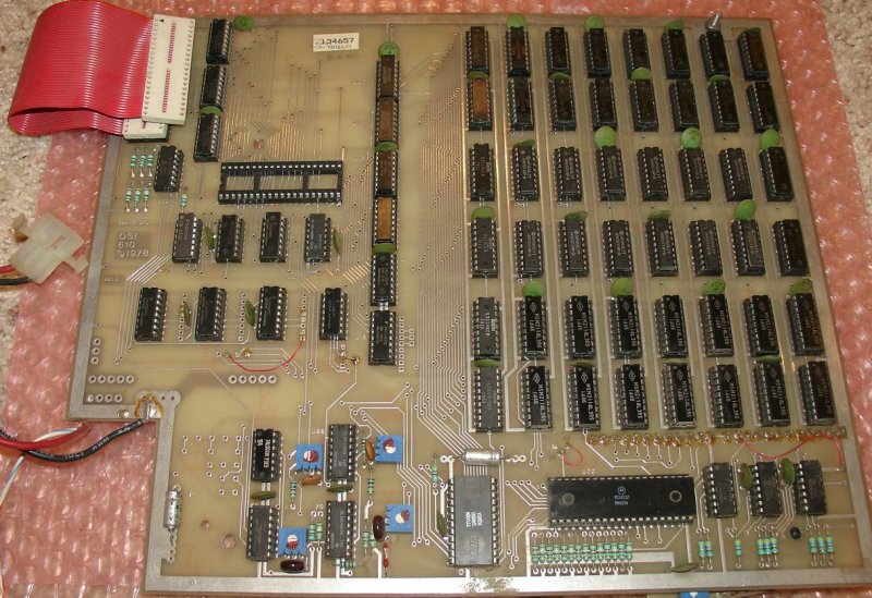
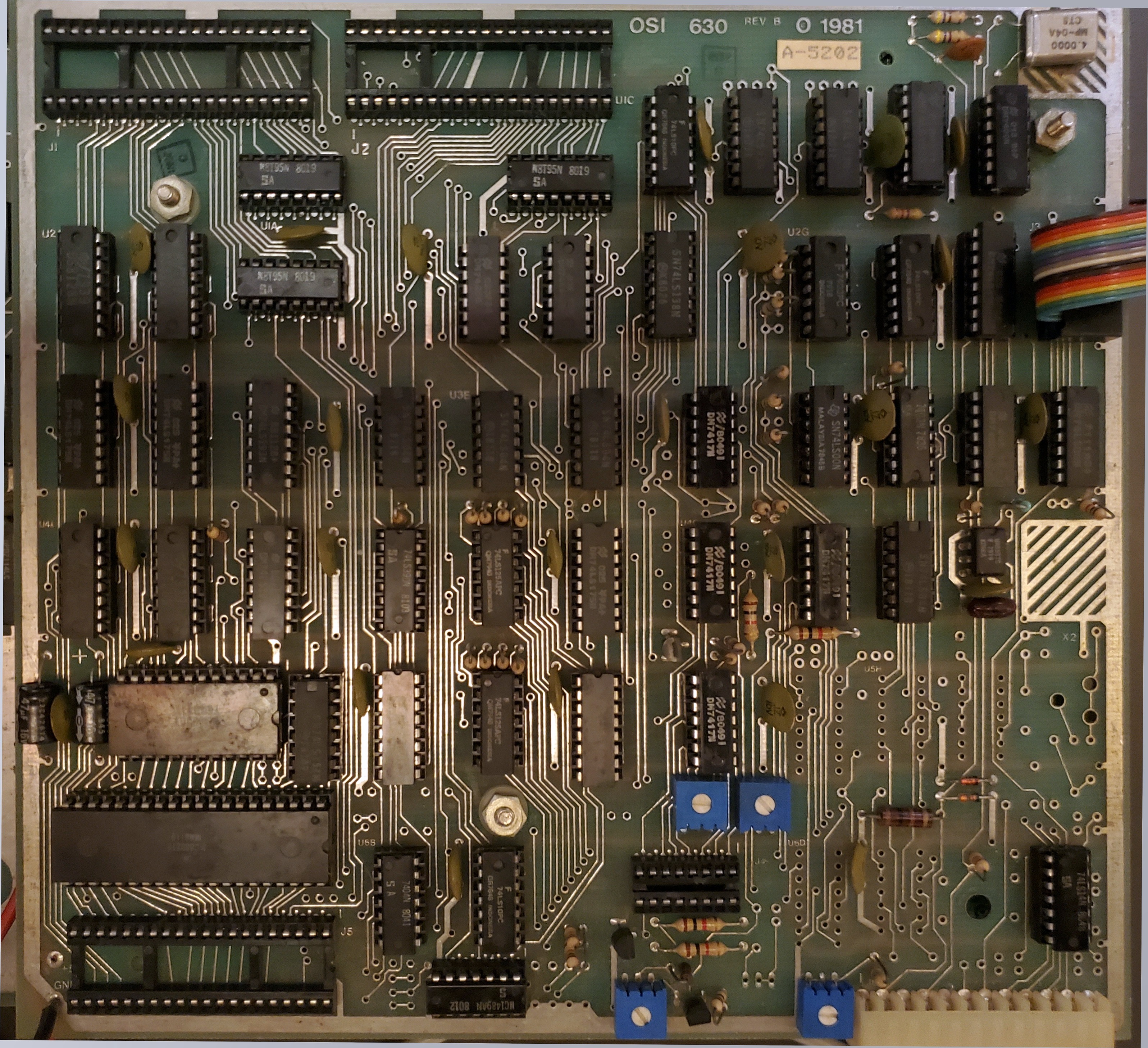
Model 630 Superboard color video expander © 1981
Color generator and I/O for C1/Superboard series II Contains AC control output, composite video color generator & RGB out, 6820 PIA, Baud rate generator & 6850 ACIA For RS-232, A15 socket for head-end cards, and a socket for the 610 disk expansion board OSI630B schematics (courtesy of Mike P) |
|||||||||||||||||||||||||||||||||||||||||||||||||||||||||||||||||||||||||||||||||||||||||||
 A12 board
|
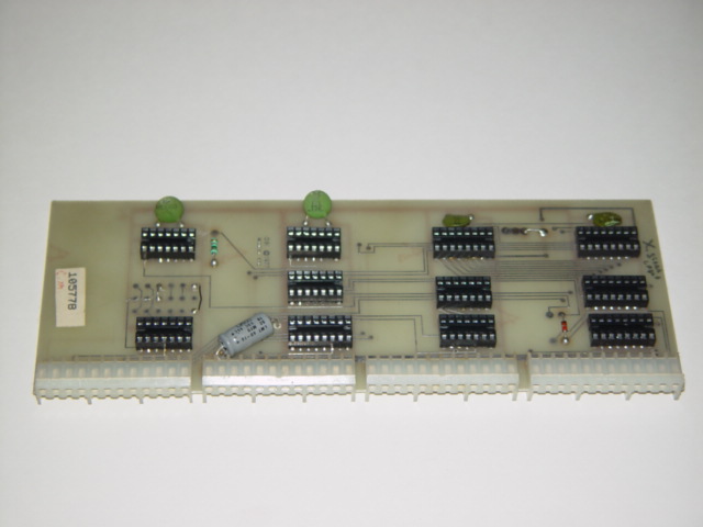
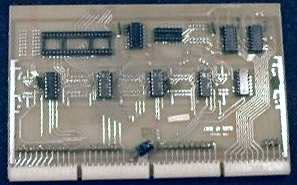
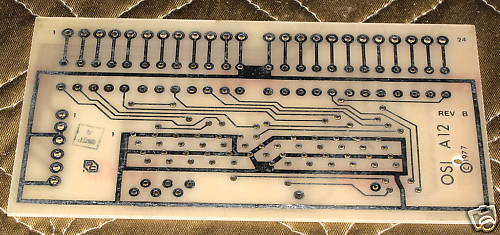
A12 interface board © 1977 Disk cable connector board for 470 Disk controller |
|||||||||||||||||||||||||||||||||||||||||||||||||||||||||||||||||||||||||||||||||||||||||||
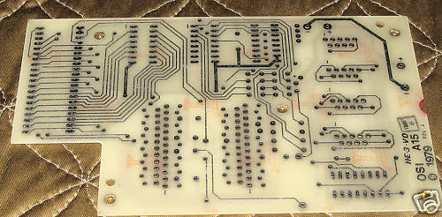
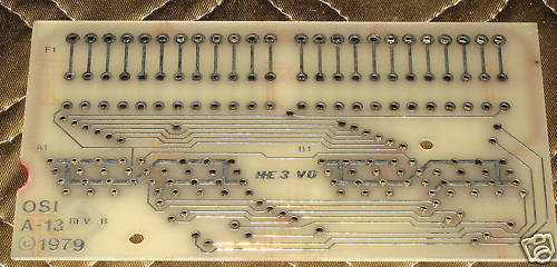 A13 board
|
A13 interface board © 1979 Disk cable connector board for 505CPU board OSI A-13 schematics (courtesy of Bill Dromgoole) |
|||||||||||||||||||||||||||||||||||||||||||||||||||||||||||||||||||||||||||||||||||||||||||
 A15 board
|
A15 interface board © 1979 Interface board for Joystick, Modem & Printer, 16 PIA lines, 16bit Head End card I/O. Populated with two DB25 connectors for serial I/O, four DB9 connectors for joysticks etc., and three 16Pin sockets for Head End cards. Interfaces to OSI 505B board via 40pin socket and ribbon cable, interfaces to OSI 542 keyboard via 16pin ribbon cable. Used in C4P-MF, C4P-DMF, & C8P-DF systems. OSI A-15 schematics (courtesy of Bill Dromgoole) |
|||||||||||||||||||||||||||||||||||||||||||||||||||||||||||||||||||||||||||||||||||||||||||
|
CA-25
Security Interface
|
CA-25 Security and AC remote interface Head End card, security and AC remote interface connects the AC-17P home security system and AC-12P wireless remote control system (X10) to C2 and C3 computers. (Interfaces to ultrasonic sensor input on BSR X-10 controller) |
|||||||||||||||||||||||||||||||||||||||||||||||||||||||||||||||||||||||||||||||||||||||||||